Documentation part 1 - decomposition view
Background
In all my years as a programmer I participated in several huge embedded software projects. A huge project, in my view, stands for a multi-board project with many of variants e.g. board to board combinations, that development lasts over a year or two. This kind of projects involve several software teams, dedicated separately to each board, group of requirement engineers, and bunch of other people, and finally, so called managers…
Working in such project and environment:
- Requires expensive complexity management
- Requires multi-level system engineering
- Suffers from communication and synchronization issues between the teams
- Needs constant and proper contractor-customer communication
- Depends on customer product specification maturity
- Requires good systems, subsystems and code documentation
There are many reasons why such a project may fail, get abandoned or rejected. Most of the IT projects does not succeed in terms of time and money. However, I do not want to yammer about a project issues, my todays goal is to elaborate a bit on software development documentation.
Software architecture
At the initial project stage selected people work on SW architecture. There is no one definition of what system architecture is.
Architecture describes the basic organization of a system. It is embodied by its individual parts and their relations between each other and to their environment, as well as by the guidelines that manage the design and the development of the system.
—IEEE Standard 1471
In general software architecture is about:
- decomposing the system into parts called components, modules, elements
- defining links between the parts by the means of interfaces
- internal interfaces (inside the developed system)
- external interfaces (for communication with outside world and environment)
- describing SW components tasks, functions and responsibilities
- presenting components interactions in functional view
System overview
In this section I would like to elaborate a bit on several aspects of the system architecture’s decomposition view. Decomposition view presents decomposed system - its parts, components, elements and modules. Lets discuss simple example of two boards:
- User interface board (UI)
- Power board (PB)
The UI board is kind of GUI that contains display and buttons. In case of washing machines UI board typically contains buttons, jog or rotator for program selection (that can be illuminated) and a display e.g. LCD or LED version. It is located at the top panel of the washing machine - everyone probably saw it… The PB board contains all drivers required for washing machine operation such as motor control driver, valves driver, heater driver, etc. By the driver I mean electronic circuitry for driving the certain actuator (motor, valve, heater).
This kind of two board solution is a typical embedded system example. Lets think a bit what both boards firmwares should look like. In my experience it is a good approach to make UI board totally stupid. It means that all the business logic and data management shall be located on the PB board. This solution has one huge advantage - if logic change is required, only PB’s firmware has to be updated and analogously if data presentation change is requested only UI’s firmware needs update. This is not always true because it is usually hard to completely decouple both boards’ software. In the previous sentence is a small cheat. There is another big reason that stands for this solution - it is an ability to replace the UI board with a different one (maybe another variant, with some extra LEDs). Now, we have the same interface to both boards UI_1 and UI_2, so that UI’s firmware can only focus on data presentation.
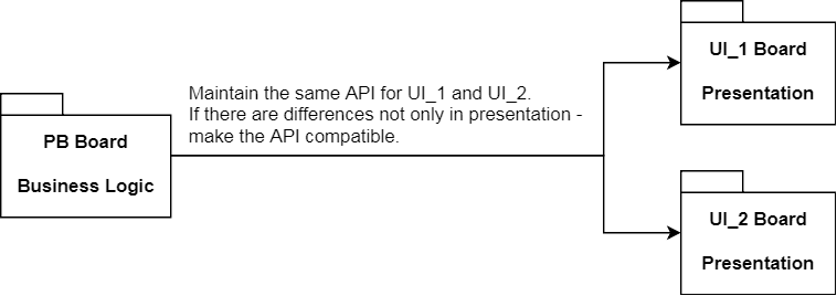
On the above picture I put a note regarding API compatibility. Lets imagine
that both boards PB and UI are connected by the UART interface. It is
reasonable to develop such UART protocol that is not prone to damage due to
protocol API extension. This can be easily justified - lets imagine the following
scenario.
- Firmware for
PBandUI_1is ready and working. - Now both
PBandUIteams start working on newUIvariant and lets call itUI_2. - New
UI_2variant has extra LED 7-segment display to show time of selected washing cycle (TTE - time to end). - Information about the TTE has to be delivered to the
UI_2board.
The scenario shows the case where additional information has to be delivered to
UI_2 board, in contrast to UI_1 board which hasn’t got this data. This
means that protocol has to be extended by e.g. adding new message that conveys
the TTE number. At this point it is not a good idea to change firmware for first
variant UI_1 - it just has to work properly when it receives TTE message
from PB. Remember both UI_1 and UI_2 boards can used interchangeably
with the same PB board and the PB board is configured in a way that
it knows the variant of UI board to work with.
Decomposition view
OK, lets come back to the topic. The decomposition view shows modules and components structure and features the links (interfaces) between those elements.
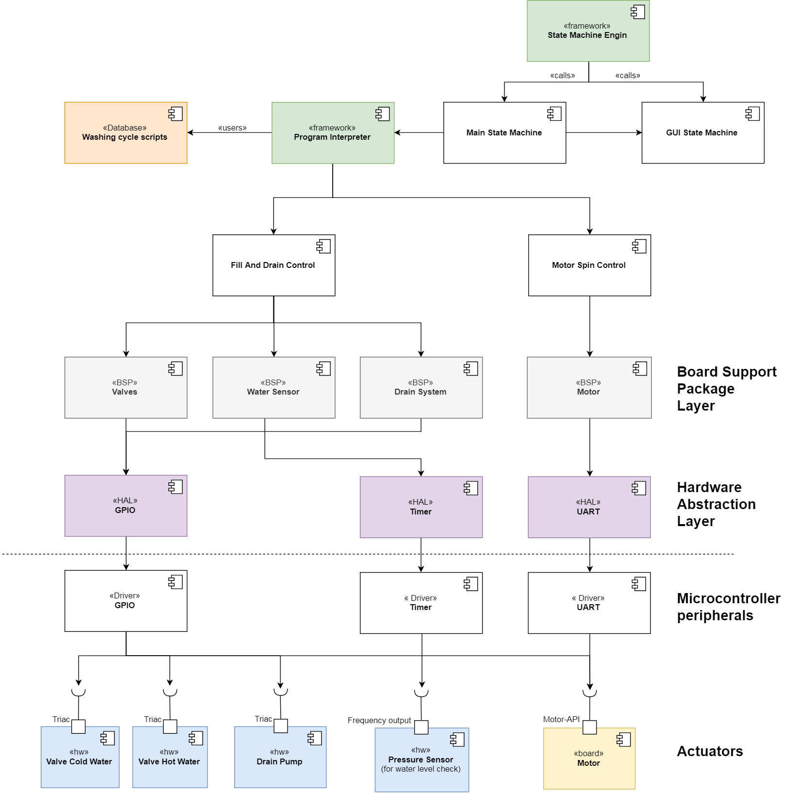
The example shows typical software decomposition view. Each component can be
treated as a .c/.h files (in C language) or as a group of those files that expose
certain API. This API can be described in the another view - class
diagram. The example features following:
- Components at the bottom represents electrical actuators and circuitries that
expose steering interface e.g.
triacgate input. - Upper layer consists of
Microcontroller Peripheral Drivers(this layer is usually provided by the microcontroller’s vendor like ST or TI) and can be easily configured by provided tools e.g. CubeMX from ST Microelectronics. - The
Hardware Abstraction layer(HAL) is a layer that abstracts microcontroller’s peripherals by exposing stable/frozen API to the application upper layers. As I said this frozen interface (bunch of predefined functions e.g. for controlling microcontroller’sGPIOs) shall not change when we replace the microcontroller from e.g. STM32 to MSP432. The only change required is to update lowerMicrocontroller Peripheral Driverslayer. - One layer above the
HALwe can findBoard Support Packagelayer. It is usually optional, however quite useful in many cases. The best example of this layer we can find in the popular dev-kits e.g. Arduino, STM32 Discovery or MSP430 Launchpad. Vendor provided examples for those boards contain predefined names for the existing hardware elements e.g. LEDs or Buttons. Take a closer look at the Arduino among the whole range of different dev-boards - they varies in hardware, while software developers use mnemonic1,2, … for digital pins andA0,A1, … for analog pins. The developer does not know which microcontroller’s port or pin is hidden behind the mnemonics. This makes it very easy for the vendor to produce various dev-kits, and developers are able to run the same software on it (no change are required - or small adjustments). Configuration of the board is done by the vendor inBoard Support Packagelayer. - The green components represent
Frameworkmodules.Frameworkis a layer that provides elements that can be used among the software layers (usually fromHALup). UsuallyFrameworklayer contains of global components (Utilities/Libraries). In the example I putProgram InterpreterandState Machine Engine. TheState Machine Enginecomponent can be treated as a scaffolding for underlaying state machines. - The
Washing cycle scriptscomponent is a database that holds washing cycles definition encoded in a custom scripting language. The scripts are used and executed by theProgram Interpreter, which understands the commands and delegates its execution to thexxx Controlcomponents (low level algorithms and actions). - The rest of the components resides in a so called
Business Logiclayer. Those modules implement the program logic (e.g. state machines for controlling the device and GUI - both communicated with each other).
Conclusion
This article defines software architecture definition and provides an example of its fundamental view which is decomposition view. The decomposition view is used to show software components and interfaces that link them together. The interface indicates what API is exposed by the particular component. The decomposition view is supplemented by the textual components description. This description should give an overview what tasks and responsibilities belongs to the components. When we develop the decomposition view is it crucial to know the interfaces between the components. It gives you the ability to correctly find missing modules or to decide whether to shift some component’s tasks to other component. In the next article I would like to present you a way how to describe the interface and how to utilize it when defining the software’s functional view.
Footnote
kaeraz, 2018/11