Documentation part 2 - interfaces and functional view
Step back
Last time I explained you software decomposition view which is one of many views of a software architecture, that you are likely to use when documenting you system. The decomposition view enables the designer to look deeply into a software system and break it down into software modules and components. I owe you an explanation what the component is. Please see below a texbook definition.
A component:
- is part of software developed for re-use
- supports information hiding
- its functionality is exposed via interfaces
- implements certain functionality
- can consist of many components (composite component)
In practice,
component is a group of source files that implements some meaningful (in terms of a system) functionality, that can be abstracted as a software part. Other software parts can operate with it through known group of methods - component’s interface. This software part can be, of course, composed of many other software parts that work together and communicate with each other in defined way. We can say that a component implements some part of the software system and can be analyzed separately from other software parts.
Interfaces
The concept of an interface enables the designers to connect system parts and understand how they communicate with each other. In other words, it shows what the component does and what doesn’t.
To be clear an precise, an interface:
- is a list of inputs (e.g. methods) that tell the component to process (do something) and give back an output (result)
- separates the declaration (which shows what things component does) from implementation (how component does the thing)
- is a contract that component supports defined interface methods
- is a black-box
The above description is a bit confusing. To put it as simply as possible,
an interface is a list of functions, methods, operations. The component which has such an interface obligates itself to implement it. By the means of the interface you are able to invoke some component’s code and get its result.
Functional view
It’s time to discuss how interfaces and components are utilized in practice. Knowing the ahead of time module’s interface has many advantages, however it is not always possible to realize. The modeling such as software designing might be a tool that can help you to examine modules communication and corresponding interfaces. Prior to modeling, you should prepare a list of use cases or functionalities that you might want to achieve by the software. Start with a big picture and break it down into smaller scenarios. Below you can find a list of exemplary functionaries in connection to filling the water into a washing machine.
- Filling shall be executed to the defined level
- It is possible to select water inlet (valve) for different program steps
- Filling shall be executed by the time manner
- Use pressure water level sensor to check water level
- Monitor water level while filling to prevent overfilling
- etc.
Below, I would like to present realization of the functionalities on a sequence diagram, pointing the usage of modules’ interfaces. Doing this on paper actually helped me to investigate what the interfaces should look like. The sequence diagram is a tool which shows particular communication scenario and features links and interactions between the software modules. Set of such dynamic diagrams forms a architecture functional view. The functional view focuses on modules communication to realize particular function of a system.
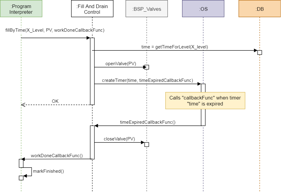
The example shows modules interactions to realize time water filling.
- The
Program Interpretermodule invokesfillByTime()method passing tree arguments:
X_Level- water level time parameter.PV- target value - herePVstands for Prewash Valve (used during prewash phase of the washing cycle).workDoneCallbackFunc- callback method, which shall be called by, theFill And Drain Controlmodule when its task is finished.
- The
Fill And Drain Controlmodule:
- Asks
DB(database) module for concrete filling time, defined byX_Levelargument.- Calls
openValue()method to open a Prewash Valve.- Creates a software timer, for the given filling time
time, and registers a callback methodtimeExpiredCallbackFunc, which is called by theOSmodule, when the time is expired.
- The
OSmodule counts timer’s time and calls atimeExpiredCallbackFunc()method, when the time is expired. - The
Fill And Drain Controlmodule:
- Closes the Prewash Valve by calling
closeValue()method.- The
workDoneCallbackFunc()callback is called back to indicate that work is done.
- The
Program Interpretermarks its task as done by calling its own interfacemarkFinished()method.
Here you can find modules’ tasks and responsibilities that are valid for the example.
| Module | Tasks and responsibilities |
|---|---|
Program Interpreter |
|
Fill And Drain Control |
|
BSP Valves |
|
OS |
|
DB |
|
Other software modules like HAL and Driver modules, are not shown on the
example for simplicity. This is your decision what level shall the sequence
diagram keep. In general, please do not be to precise. Some details are just
clear for the developers.
Conclusion
Software modules shall implement certain functionalities. Separation of the functionalities into modules helps to keep the system decoupled. Each module should realize only limited tasks and for that reason developers should keep in mind Single Responsibility Principle. Having a software system broken down into components, you are able to show modules’ interactions on a so called functional view. The sequence diagram can be used for that purpose. Bear in mind, that prior to modeling sequence diagrams, you may not be able to break down a software system into parts. This is normal and do not blame yourself for being undecided. Use all architectural views and diagrams to investigate the system. Take your time to try many approaches and after getting enough experience, you will be sure which approach suits best for you.
Footnote
kaeraz, 2018/12